
Compare Equipment Go Back
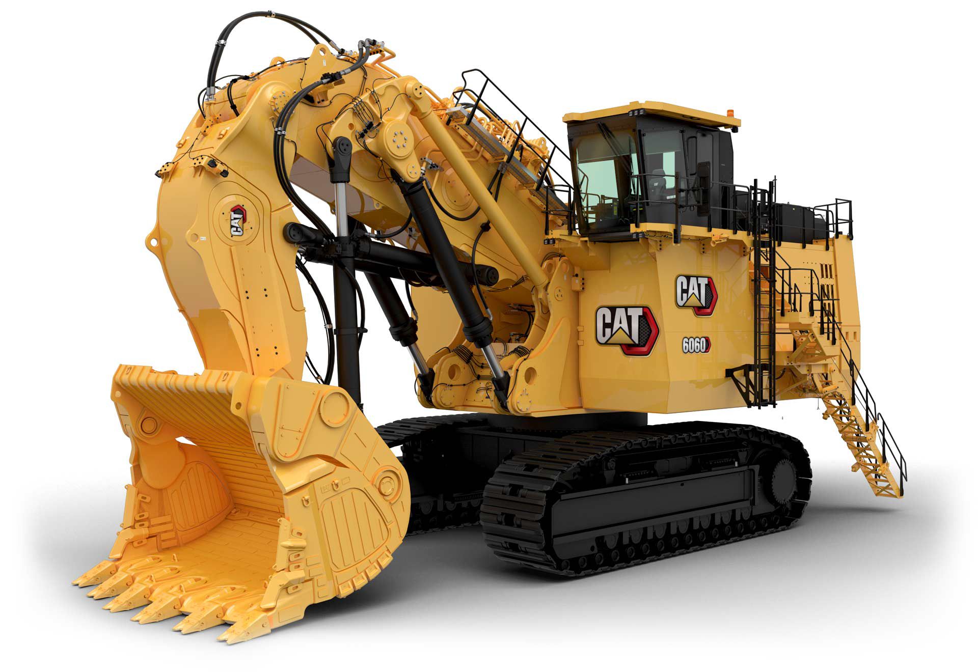 6060 Hydraulic Mining Shovel |
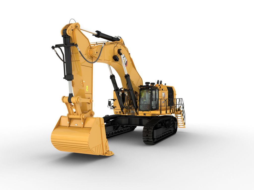 6015 Hydraulic Shovel |
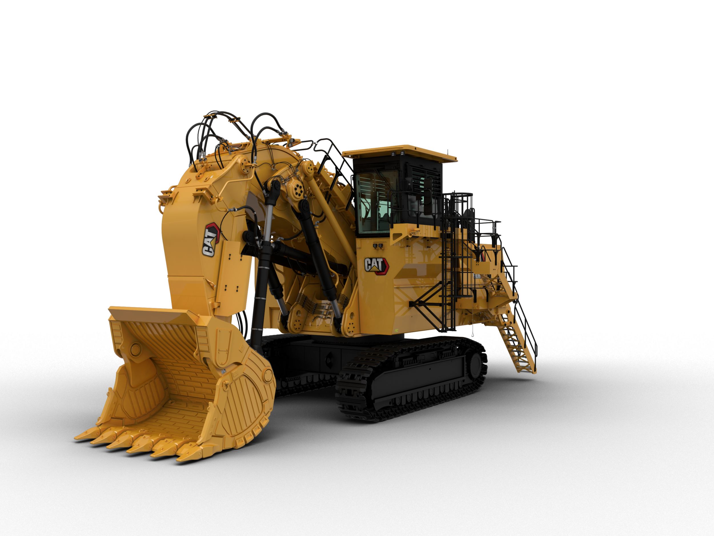 6030 Hydraulic Shovel |
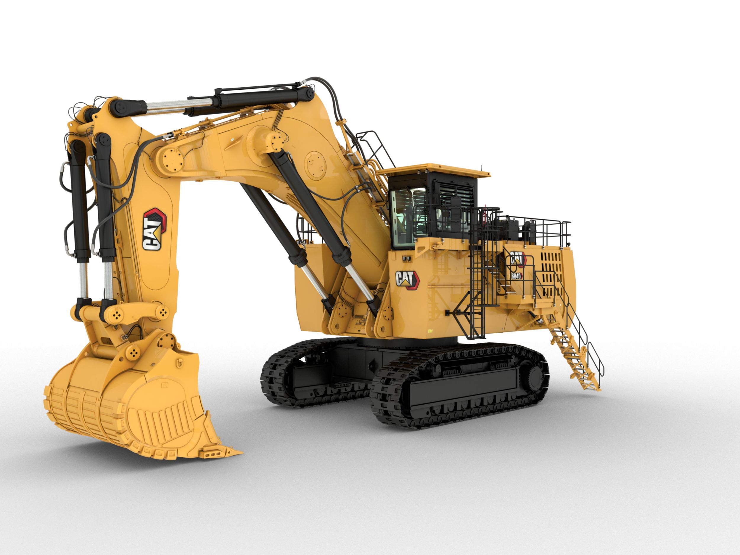 6040 Hydraulic Mining Shovel |
|
General |
||||
|---|---|---|---|---|
| Engine Output - SAE J1995 | 3015 HP | 824 HP | 1649 HP | 2079 HP |
| Bucket Payload | 67 ton (US) | 16.1 ton (US) | 33 ton (US) | 43.7 ton (US) |
| Operating Weight | 660 ton (US) | 154.3 ton (US) | 324 ton (US) | 446 ton (US) |
| Note | Specifications shown above apply to Face Shovel configuration. Backhoe and Frontless configurations are also available. | Specifications shown above apply to highly regulated, backhoe configuration. Lesser regulated and frontless configurations are also available. | Specifications shown above apply to the highly regulated Face Shovel configuration. Backhoe and Frontless configurations are also available for all regions. | Specifications above apply to the HRC Face Shovel configuration. Backhoe and Frontless configurations are also available for both HRC and LRC. |
Engine |
||||
| Engine Model | 2 x Cat 3512E | - | - | 2 x Cat C32 |
| Emissions | - | U.S. EPA Tier 4 Final and EU Stage V; China Nonroad Stage III, equivalent to U.S. EPA Tier 2; Equivalent to U.S. EPA Tier 1 | - | - |
| Gross Power - SAE J1995 | - | - | - | 2079 HP |
| Net Power - SAE J1349 | - | - | - | 1915 HP |
| Note | - | - | - | Power output relates to highly regulated engines. Lesser regulated engines are also available. |
Diesel Engines |
||||
| Rated Speed | 1,800 min-1 (1,800 rpm) | - | - | - |
| Number of Cylinders - Each Engine | 12 | - | 12 | 12 |
| Bore | 6.69 in | - | 5.42 in | 5.71 in |
| Stroke | 8.46 in | - | 6 in | 6.38 in |
| Displacement | 3574 in³ | - | 1648 in³ | 1959 in³ |
| Aspiration | Turbocharged and charge air-cooled | - | Turbocharged and air-to-air aftercooled | Turbocharged and air-to-air aftercooled |
| Components (1) | Non-DEF Aftertreatment system with Diesel Oxidation Catalysts (DOCs) | - | Hydraulically driven radiator fan with electronically controlled fan speed | Additional high-capacity water separator |
| Components (2) | High-capacity water separator | - | Micro processed engine management | Two-stage fuel filter including water separator |
| Components (3) | Two-stage fuel filter with series filtration | - | Heavy-duty air filters | Heavy-duty air filters |
| Components (4) | Heavy-duty air filters | - | Two-stage fuel filter, including water separator | Microprocessed engine management |
| Components (5) | Microprocessed engine management | - | Additional high-capacity water separator | Hydraulically driven radiator fan with electronically controlled fan speed |
| Components (6) | Hydraulically driven radiator fan with electronically controlled fan speed | - | - | - |
| Components (7) | Exhaust manifold and turbo heat shields | - | - | - |
| Emissions | - | - | Meets U.S. EPA Tier 4 Final and EU Stage V emission standards | Meets U.S. EPA Tier 4 Final and EU Stage V emission standards |
| Fuel Tank Capacity | - | - | 1342 gal (US) | 2098 gal (US) |
Diesel Engine - Lesser Regulated |
||||
| Gross Power - SAE J1995 | 3025 HP | - | 1531 HP | - |
| Net Power - ISO 9249 | 2990 HP | - | 1511 HP | - |
| Net Power - SAE J1349 | 2821 HP | - | 1425 HP | - |
| Emissions | Optimized for fuel consumption. | - | Meets China Nonroad Stage III emission standards, equivalent to U.S. EPA Tier 2 | - |
Diesel Engine - Highly Regulated |
||||
| Gross Power - SAE J1995 | 3015 HP | - | 1649 HP | - |
| Net Power - SAE J1349 | 2810 HP | - | 1541 HP | - |
| Net Power - ISO 9249 | 2979 HP | - | 1625 HP | - |
| Emissions | Meets U.S. EPA Tier 4 Final emission requirements. These engines participate in the U.S. EPA averaging, banking, and trading provisions. | - | Meets U.S. EPA Tier 4 Final and EU Stage V emission standards | - |
Electrical System |
||||
| System Voltage | 24 V | 24 V | - | - |
| Batteries in Series/Parallel Installation | 6 x 210 Ah; 12 V each; 630 Ah 24 V in total | - | - | - |
| Components (1) | 6 maintenance-free batteries | Emergency stop in cabin, engine module, pump room and on service station accessible from ground level | - | - |
| Components (2) | Lockable battery isolator switch | Four maintenance free batteries | - | - |
| Components (3) | Lockable starter isolator switch | Lockable battery isolation switch | - | - |
| Components (4) | 13 LED high-brightness working flood lights | 5 LED service lights | - | - |
| Components (5) | 17 LED service lights | 14 LED high-brightness working lights | - | - |
| Components (6) | 2 electric horns (1 cab module; 1 oil cooler module) | 2 electric horns | - | - |
| Batteries | - | 4 × 200 Ah (12 V each) | 4 maintenance-free batteries | - |
| Alternator Rating | - | 150 A (24 V) in total | - | - |
| Components (7) | - | Two (2) lights for rear end | - | - |
| Components (9) | - | One (1) beacon light on cabin roof | - | - |
| Components (8) | - | One (1) light for machine deck/service | - | - |
Operating Weights |
||||
| 6060 FS - Standard Track Pads | 4.58 ft | - | - | - |
| 6060 FS - Operating Weight | 1320110 lb | - | - | - |
| 6060 FS - Ground Pressure | 26.6 N/cm2 (38.5 psi) | - | - | - |
| Backhoe - Standard Track Pads | 4.58 ft | - | - | - |
| Backhoe - Operating Weight | 1323860 lb | - | - | - |
| Backhoe - Ground Pressure | 26.7 N/cm2 (38.7 psi) | - | - | - |
| Note | Operating weights include: base machine, front attachment, standard track pads, standard rock bucket, 100% fuel and lubricants. | - | Other track pads available on request. Operating weights include: base machine, front attachment, standard track pads, standard rock bucket, and 100% fuel and lubricants. | 1600 mm track pads available as option |
| 6030 FS - Standard Track Pads | - | - | 3.25 ft | - |
| 6030 FS - Operating Weight | - | - | 657640 lb | - |
| 6030 FS - Ground Pressure | - | - | 32.2 psi | - |
| 6030 - Standard Track Pads | - | - | 3.25 ft | - |
| 6030 - Operating Weight | - | - | 660060 lb | - |
| 6030 - Ground Pressure | - | - | 32.3 psi | - |
| 6040 FS - Standard Track Pads | - | - | - | 3.9 ft |
| 6040 FS - Operating Weight | - | - | - | 891980 lb |
| 6040 FS - Ground Pressure | - | - | - | 24.1 N/cm2 (35.0 psi) |
| 6040 - Standard Track Pads | - | - | - | 3.9 ft |
| 6040 - Operating Weight | - | - | - | 897930 lb |
| 6040 - Ground Pressure | - | - | - | 24.3 N/cm2 (35.3 psi) |
| 6040 FS - Note | - | - | - | Other track pads available on request |
Service Refill Capacities |
||||
| Fuel Tank | 3136 gal (US) | 449 gal (US) | - | - |
| Hydraulic Tank | 1876 gal (US) | 253 gal (US) | - | - |
| Hydraulic System - Including Tank | 2483 gal (US) | 463 gal (US) | - | - |
| Engine Oil | 86.6 gal (US) | 23 gal (US) | - | - |
| Cooling System | 211.4 gal (US) | 44 gal (US) | - | - |
| Swing Drive | 42.4 gal (US) | 2.4 gal (US) | - | - |
| Grease Tank | 188 gal (US) | 18 gal (US) | - | - |
Hydraulic System with Pump Managing System |
||||
| Main Pumps - Diesel Version | 8 variable swash plate pumps | - | - | 4 x variable swash plate pumps |
| Main Pumps - Maximum Oil Flow - Diesel Version | 8 x 650 L/min (8 x 172 gal/min) | - | 4 x 552 L/min (4 x 146 gal/min) | 4 x 724 L/min (4 x 191 gal/min) |
| Maximum Pressure - Attachment | 4640 psi | - | 4495 psi | 4350 psi |
| Maximum Pressure - Travel | 5220 psi | - | 5220 psi | 5080 psi |
| Swing Pumps - Diesel Version | 4 reversible swash plate pumps | - | - | 4 x reversible swash plate pump |
| Swing Pumps - Maximum Oil Flow - Diesel Version | 4 x 352 L/min (4 x 93 gal/min) | - | 4 x 197 L/min (4 x 52 gal/min) | 4 x 321 L/min (4 x 85 gal/min) |
| Maximum Pressure - Swing Pumps | 5075 psi | - | 5076 psi | 5080 psi |
| Hydraulic Tank Capacity - Approximately | - | - | 707 gal (US) | - |
| Total Volume of Hydraulic Oil - Approximately | - | - | 925 gal (US) | - |
| Main Pumps | - | - | 4 x variable swash plate pumps | - |
| Swing Pumps | - | - | 2 x reversible swash plate double pumps | - |
| Hydraulic Tank Capacity - Diesel Version - Approximately | - | - | - | 898 gal (US) |
| Total Volume of Hydraulic Oil - Diesel Version - Approximately | - | - | - | 1532 gal (US) |
Hydraulic Oil Cooling |
||||
| Oil Flow of Cooling Pumps | 4 x 488 L/min (4 x 129 gal/min) | - | - | - |
| Components | 4 cooling fans | - | - | - |
| Diameter - Fan | 46 in | - | 48 in | 2 × 1524 mm (2 × 60 in) |
| Features (1) | Cooling system fully independent of all main circuits, i.e. controlled cooling capacity is available whenever engine is running | - | - | Cooling system fully independent of all main circuits, i.e. controlled cooling capacity is available whenever engine is running |
| Features (2) | Fan speed and flow of oil to the coolers are thermostatically controlled | - | - | Fan speed is thermostatically controlled |
| Features (3) | Extremely high cooling efficiency to ensure optimum oil temperature | - | - | Extremely high cooling efficiency to ensure optimum oil temperature |
| Features (4) | Gear-type cooling pumps supplying high-volume, low-pressure oil to fans and aluminum coolers | - | - | - |
| Oil Flow of Cooling Pumps - Diesel Version | - | - | 2 x 467 L/min (2 x 123 gal/min) | 2 x 799 L/min (2 x 211 gal/min) |
| Components (1) | - | - | - | Gear type cooling pumps supplying high-volume, low-pressure oil to aluminum coolers |
| Components (2) | - | - | - | Variable axial piston pumps supplying low-volume, high-pressure oil to fans |
Swing System |
||||
| Swing Drive | 4 compact planetary transmissions with axial piston motors | Two (2) compact planetary transmissions with axial piston motors | 2 compact planetary transmissions with axial piston motors | 3 compact planetary transmissions with axial piston motors |
| Parking Brakes | Wet multiple disc brake, spring loaded/hydraulically released | - | Wet multiple-disc brake, spring-loaded/hydraulically released | - |
| Maximum Swing Speed | 3.8 r/min | 4.9 r/min | - | - |
| Swing Ring | Triple-race roller bearing with sealed internal gearing | Cross roller bearing with sealed internal gearing | Triple-race roller bearing with sealed internal gearing | Triple-race roller bearing with sealed internal gearing |
| Features (1) | Dirt wipers at swing ring to prevent build-up of debris between swing ring and carbody | Closed-loop swing circuit with speed control | - | Dirt wipers at swing ring to prevent build-up of debris between swing ring and carbody |
| Features (2) | Closed-loop swing circuit with torque control | Hydraulic braking of swing motion when control is returned to neutral position or by counteracting control for stronger braking | - | Closed-loop swing circuit with torque control |
| Features (3) | Hydraulic braking of the swing motion by counteracting control | All raceways and the internal gearing of swing ring supplied by automatic central lubrication system | - | Hydraulic braking of the swing motion by counteracting control |
| Features (4) | All raceways and the internal gearing of swing ring, supplied by automatic central lubrication system | - | - | All raceways and the internal gearing of swing ring supplied by automatic central lubrication system |
| Parking Brake | - | Wet multiple disc brake, spring-loaded/hydraulically released | - | Wet multiple disc brake, spring-loaded/hydraulically released |
| Maximum Swing Speed - Diesel Version | - | - | 4.6 r/min | 4.7 r/min |
| Maximum Swing Speed - AC Version | - | - | 5 r/min | - |
Undercarriage |
||||
| Travel Speed - 1st Stage - Maximum | 0.68 mile/h | - | 0.87 mile/h | 0.93 mile/h |
| Travel Speed - 2nd Stage - Maximum | 0.99 mile/h | - | 1.68 mile/h | 1.55 mile/h |
| Maximum Tractive Force | 661160 lb | 197157 lbf | 360144 ft·lbf | 471260 lb |
| Gradeability - Travel Drives - Maximum | 39 % | - | - | 57 % |
| Track Pads - Each Side | 42 | - | 44 | 42 |
| Bottom Rollers - Each Side | 7 | - | 7 | 7 |
| Support Rollers - Each Side | 2 plus a skid plate in between | - | 2 plus a skid plate in between | 2 plus a skid plate in between |
| Travel Drives - Each Side | 1 planetary transmission with 2 two-stage axial piston motors | - | 1 planetary transmission with 2 two-stage axial piston motors | 1 planetary transmission with 2 two-stage axial piston motors |
| Components (1) | HD tracks with cast double-grouser track pad | Forged double-grouser track pads | All running surfaces of sprockets, idlers, rollers and pad links, as well as teeth contact areas of sprocket and pad links, are hardened | All running surfaces of sprockets, idlers, rollers and track links are hardened |
| Components (2) | HD fixed axle rollers and idlers | Chain links connected by hardened pins and bushings | Cast double-grouser combined pad-links with bushings connected by hardened full floating pins | Acoustic travel alarm |
| Components (3) | Hardened running surfaces of sprockets, idlers, rollers, pad links, and teeth contact areas | Postive Pin Retention (PPR2) sealed and greased track design | Fully hydraulic self-adjusting track tensioning system with membrane accumulator | Cast double-grouser combined pad-links with bushings connected by hardened full floating pins |
| Components (4) | Acoustic travel alarm (forward and reverse) | All running surfaces of sprockets, idlers, rollers and track chain links hardened | Automatic hydraulic retarder valve to prevent over-speed on downhill travel | All teeth contact areas of sprocket and pad links are hardened |
| Components (5) | Fully hydraulic, self-adjusting track tensioning system with piston accumulator | Fully hydraulic self-adjusting track tensioning system with accumulator | Acoustic travel alarm | Fully hydraulic self-adjusting track tensioning system with membrane accumulator |
| Components (6) | Automatic hydraulic retarder valve to prevent over-speed on downhill travel | Automatic hydraulic retarder valve to prevent overspeed on downhill travel | - | Automatic hydraulic retarder valve to prevent over-speed on downhill travel |
| Travel Speed - Two Stages - 1st Stage - Maximum | - | 1.6 mile/h | - | - |
| Travel Speed - Two Stages - 2nd Stage - Maximum | - | 2.3 mile/h | - | - |
| Maximum Drawbar Pull - Forward | - | 192886 lbf | - | - |
| Maximum Drawbar Pull - Reverse | - | 220987 lbf | - | - |
| Gradeability - Travel Drives | - | 38°/78% (SAE J1309) | - | - |
| Hydraulic Track Tensioning | - | With accumulator | - | - |
| Number of Shoes - Each Side | - | 46 | - | - |
| Number of Track Rollers - Each Side | - | 9 | - | - |
| Number of Carrier Rollers - Each Side | - | 3 | - | - |
| Components (7) | - | Audible travel alarm | - | - |
| Gradeability - Travel Drives - Approximate | - | - | 47 % | - |
| Parking Brakes | - | - | Wet multiple disc brake, spring loaded/hydraulically released | - |
| Parking Brake | - | - | - | Wet multiple disc brake, spring applied/hydraulically released |
Operator's Cab |
||||
| Operator's Eye Level - Approximately | 24.91 ft | - | 21.33 ft | 22.31 ft |
| Internal Dimensions of Cab - Length | 7.33 ft | - | 7.22 ft | 7.22 ft |
| Internal Dimensions of Cab - Width | 5.33 ft | - | 5.25 ft | 5.25 ft |
| Internal Dimensions of Cab - Height | 6.75 ft | - | 7.05 ft | 7.05 ft |
| Components (1) | Single hydraulically driven HVAC System, with dual system option | Pressurized operator station with positive filtration | Under roof mounted heating ventilating and air conditioning system | Switch in seat cushion to automatically neutralize the hydraulic controls when operator leaves the seat |
| Components (2) | In-floor window with removable grate | Heated cab mirror | External sun shields at side and rear windows | Pneumatically cushioned and multi-adjustable comfort seat with lumbar support, seat heating, safety belt, head- and armrests |
| Components (3) | Pneumatically cushioned and multi-adjustable comfort seat with heating, cooling, and lumbar support | Sliding upper door window (left-hand cab door) | Robust instrument panel including large colored BCS screen with transflective technology | Roller blinds at all windows |
| Components (4) | Independently adjustable seat consoles with integrated joysticks | Glass-breaking safety hammer | Board Control System (BCS) electronic monitoring and data logging system for vital signs and service data of engines, hydraulic system and lubrication system | Windshield with parallel intermittent wiper/washer |
| Components (5) | Operator Protective Guard (Top Guard) (ISO 10262:1998) | Removable lower windshield with in cab storage bracket | Hydraulically operated 45 degree access stairway | All-round safety glass, armored windshield and sliding side window |
| Components (6) | Elevated full-size trainer seat with safety belt and laptop desk | Joystick Controls Alternate Patterns including ISO/JIS, BHL, MHI, KOBE, or SCM | Emergency egress ladder with ladder cage | Operator Protective Guard (Top Guard) |
| Components (7) | Additional fold-away auxiliary seat with safety belt | Beverage holder | Switch in seat cushion to automatically neutralize the hydraulic controls when operator leaves the seat | Single HVAC with option for Dual HVAC |
| Components (8) | Operator Presence switch | Literature holder | Pneumatically cushioned and multi-adjustable comfort seat with lumbar support, seat heating, safety belt, head- and armrests | Joystick controls integrated in independently adjustable seat consoles |
| Components (9) | Monitoring system with 254 mm (10 in) touch screen | AM/FM radio | Roller blinds at all windows | Fold-away auxiliary seat with safety belt |
| Components (10) | Powered 45 degree access stairway | Radio with MP3 auxiliary audio port | Windshield with parallel intermittent wiper/washer | External sun shields at side and rear windows |
| Components (11) | Emergency egress ladder | Two stereo speakers | All-round safety glass, armored windshield and sliding side window | Sliding emergency ladder (kick-down type) with ladder cage |
| Components (12) | FM/AM radio with USB and AUX input | Storage shelf suitable for lunch or toolbox | Operator Protective Guards (ISO 10262:1998 Level II | Machine access via retractable access stairway, stairway angle approximately 45 degrees, hydraulically operated |
| Components (13) | Roller blinds on 3 front windows | Color LCD display with warning, filter/fluid change, and working hour information | Joystick controls integrated in independently adjustable seat consoles | Robust instrument panel including large colored BCS screen with transflective technology |
| Components (14) | 3 cup holders | Adjustable armrest | Fold-away auxiliary seat with safety belt | - |
| Components (15) | Cat Electronic Technician service port | Height-adjustable joystick consoles | - | - |
| Components (16) | - | Neutral lever (lock out) for all controls | - | - |
| Components (17) | - | Travel control pedals with removable hand levers | - | - |
| Components (18) | - | Two power outlets, 10 amp (total) | - | - |
| Components (19) | - | Laminated glass front upper window and tempered other windows | - | - |
| Board Control System (BCS III) Features (1) | - | - | - | USB, Lan (TCP/IP) and CAN BUS interfaces for data export |
| Board Control System (BCS III) Features (2) | - | - | - | On-screen PDF documentation (e.g. operating instructions, technical handbook, spare parts catalog, electric circuit diagram) |
| Board Control System (BCS III) Features (3) | - | - | - | Robust instrument panel including large (12 in) colored touch screen for intuitive handling |
| Board Control System (BCS III) Features (4) | - | - | - | Electronic monitoring, data logging & diagnostic system for vital signs & service data of engines, hydraulic & lube systems |
| Board Control System (BCS III) Features (5) | - | - | - | On-screen troubleshooting assistance |
| Board Control System (BCS III) Features (6) | - | - | - | Graphic charts of logged data |
| Board Control System (BCS III) Features (7) | - | - | - | Fault memory with storage of related conditions |
Automatic Lubrication System |
||||
| Capacity - Grease Container | 188 gal (US) | - | 119 gal (US) | 188 gal (US) |
| Type (1) | Dual-circuit system with hydraulically driven heavy-duty pumps and electronic time relay control to adjust the pause/lube times | Central bank lubrication system | Dual-circuit system with hydraulically driven heavy-duty pump and electronic time relay control to adjust the pause/lube times | Dual-circuit system with hydraulically driven heavy-duty pumps and electronic time relay control adjust the pause/lube times |
| Type (2) | System failures displayed by monitoring system | Grease is automatically applied to all attachment pivot points (except bucket linkage) and slew bearing | Connected to the lubrication system are the swing roller bearing with internal gearing and all pivot points of attachment, bucket and cylinders | System failures displayed by Board Control System |
| Type (3) | Grease filters (200 µm) between service station and container as well as directly behind grease pump | Standard grease reel on machine for bucket linkage | Lubricated pinion for greasing of internal gearing of swing ring | Grease filters (200 µm) between service station and container, as well as directly behind grease pump |
| Type (4) | Main lube system connections include: pivot points of attachment, bucket and cylinders, raceways of swing roller bearing, and 2 greasing pinions for the internal gearing of swing ring | Grease refill service point accessible from ground | System failures displayed by Board Control System | Connected to the lubrication system are: - pivot points of attachment, bucket and cylinders |
| Capacity - Grease Barrel | - | 18 gal (US) | - | - |
| Type (5) | - | - | Grease filters between service station and container as well as directly behind grease pump | Connected to the lubrication system are: - raceways of the swing roller bearing - two greasing pinions for the internal gearing of the swing ring |
Attachments |
||||
| Shovel attachment with unique TriPower kinematics ensuring the following main features: (1) | Automatic roll-back limiter to prevent material spillage; Kinematic assistance to hydraulic forces | - | Automatic roll-back limiter to prevent material spillage and kinematic assistance to hydraulic forces | - Automatic roll-back limiter to prevent material spillage - Kinematic assistance to hydraulic forces |
| Shovel attachment with unique TriPower kinematics ensuring the following main features: (2) | Horizontal Automatic constant-angle bucket guidance; Vertical Automatic constant-angle bucket guidance | - | Horizontal automatic constant-angle bucket guidance and vertical automatic constant-angle bucket guidance | - Horizontal automatic constant-angle bucket guidance - Vertical automatic constant-angle bucket guidance |
| Shovel attachment with unique TriPower kinematics ensuring the following main features: (3) | Constant boom momentum throughout the entire lift arc; Crowd force assistance | - | Constant boom momentum throughout the whole lift arc and crowd force assistance | - Constant boom momentum throughout the whole lift arc - Crowd force assistance |
| All buckets (FS and BH) are equipped with a wear package consisting of: (1) | Special liner material covering main wear areas inside and outside of bucket and lip shrouds between teeth | - | Special liner material covering main wear areas inside and outside of bucket and lip shrouds between teeth | - Special liner material covering main wear areas inside and outside of bucket - Lip shrouds between teeth |
| All buckets (FS and BH) are equipped with a wear package consisting of: (2) | Wing shrouds on side walls and heel shrouds at bottom edges | - | Wing shrouds on side walls and heel shrouds at bottom edges | - Wing shrouds on side walls - Heel shrouds at bottom edges |
| Type (1) | Catwalks with rails at booms (FS and BH) | Boom and stick torsion-resistant with welded box design | Catwalks with rails at booms | Inspection hole in monoboom BH |
| Type (2) | Guards for shovel cylinders (FS) | High-tensile steel with solid steel castings at pivot areas | Special wear packages for highly abrasive materials on request | Pressure-free lowering of boom (FS and BH) and stick (FS) by means of a float valve |
| Type (3) | Pressure-free lowering of boom (FS and BH) and stick (FS) by means of a float valve | Boom and stick stress-relieved after welding | Pressure-free lowering of boom (FS and BH) and stick (FS) by means of a float valve | Special wear packages for highly abrasive materials on request |
| Type (4) | Service access holes from both sides of boom (FS and BH) and stick (FS) | Float valve for boom down function | Welding procedures allow for internal counter-welding (double prep weld) wherever possible | Catwalks with rails at boom (FS and BH) |
| Type (5) | Welding procedures allow for internal counter-welding (double prep weld) wherever possible | - | Booms and sticks are stress-relieved after welding | Welding procedures allow for internal counter-welding (double prep weld) wherever possible |
| Type (6) | Booms and sticks are stress-relieved after welding | - | Booms and sticks are torsion-resistant, welded box design of high-tensile steel with solid steel castings at pivot areas | Boom and sticks are stress-relieved after welding |
| Type (7) | Booms and sticks are torsion-resistant, welded box design of high-tensile steel with massive steel castings at pivot areas | - | - | Boom and sticks are torsion-resistant, welded box design of high-tensile steel with massive steel casting at pivot areas |
| Type (8) | Special wear packages for highly abrasive materials available upon request | - | - | Guards for shovel cylinders (FS) |
| Buckets Equipped With | - | – Special liner material covering main wear areas inside and outside – Lip shrouds – Wing shrouds – Heel shrouds | - | - |
Digging Forces |
||||
| Maximum Crowd Force | 494410 lb | - | 291700 ft·lbf | - |
| Maximum Breakout Force | 388780 lb | - | - | - |
| Maximum Tearout Force | - | - | 212150 ft·lbf | - |
Working Ranges |
||||
| Maximum Digging Height | 51.17 ft | - | - | - |
| Maximum Digging Reach | 54.17 ft | - | - | - |
| Maximum Digging Depth | 9.17 ft | - | - | - |
Standard Bucket Capacity |
||||
| Face Shovel (heaped 2:1) | 44.5 yd³ | - | - | - |
| Backhoe (heaped 1:1) | 44.5 yd³ | - | - | - |
Backhoe Attachment (BH) - Digging Forces |
||||
| Stick Digging Force - ISO | 295740 lb | 104761 lbf | - | - |
| Bucket Digging Force - ISO | 274840 lb | 120947 lbf | - | - |
| Bucket Digging Force - SAE | - | 112600 lbf | - | - |
| Stick Digging Force - SAE | - | 98800 lbf | - | - |
Backhoe Attachment (BH) - Working Range |
||||
| Maximum Digging Height | 52.83 ft | 41.9 ft | - | - |
| Maximum Digging Reach | 62.33 ft | 45.6 ft | - | - |
| Maximum Digging Depth | 29.17 ft | 26.3 ft | - | - |
| Maximum Dump Height | - | 27.9 ft | - | - |
Retractable Service Station |
||||
| Installation | Retractable service station installed underneath the engine module and easily accessible from ground. | - | - | Retractable service station installed underneath the engine module and easily accessible from ground |
| Equipped With (1) | Quick couplings for: Diesel fuel, Engine coolant - left/right engine, Pump transmission gear oil - left/right engine, Engine oil - left/right engine, Hydraulic oil tank, and grease container | - | - | - |
| Equipped With (2) | Cat jump-start socket | - | - | - |
| Equipped With (3) | Indicator lights | - | - | - |
Engine - U.S. EPA Tier 4 Final |
||||
| Engine Model | - | Cat® C27 | - | - |
| Gross Power - SAE J1995 | - | 824 HP | - | - |
| Net Power - SAE J1349 | - | 746 HP | - | - |
Engine - Cat C27 with Tier 4 Final Emission Standards |
||||
| Number of Cylinders | - | 12 | - | - |
| Bore | - | 5.4 in | - | - |
| Stroke | - | 6 in | - | - |
| Displacement | - | 1648 in³ | - | - |
Engine - Equivalent to U.S. EPA Tier 2 |
||||
| Engine Model | - | Cat® C27 | - | - |
| Gross Power - SAE J1995 | - | 839 HP | - | - |
| Net Power - SAE J1349 | - | 746 HP | - | - |
Engine - Cat C27 with Tier 1 or Tier 2 Equivalent Emission Standards |
||||
| Number of Cylinders | - | 12 | - | - |
| Bore | - | 5.4 in | - | - |
| Stroke | - | 6 in | - | - |
| Displacement | - | 1648 in³ | - | - |
| Aspiration | - | Turbocharged and air-to-air aftercooled | - | - |
Operating Weights - Backhoe |
||||
| Operating Weight | - | 154 ton (US) | - | - |
Weights |
||||
| Ground Pressure | - | 23.6 psi | - | - |
| Note | - | Operating weight includes: 700 mm (28 in) track shoes, 7.6 m (24 ft 11 in) boom, 3.4 m (11 ft 2 in) stick, standard rock bucket, 100% fuel and lubricants | - | - |
| Operating Weight | - | 308000 lb | - | - |
Track |
||||
| Standard | - | 28 in | - | - |
| Wide | - | 36 in | - | - |
| Extra Wide | - | 39 in | - | - |
| Number of Shoes - Each Side | - | 46 | - | - |
| Number of Track Rollers - Each Side | - | 9 | - | - |
| Number of Carrier Rollers - Each Side | - | 3 | - | - |
| Track Pads | - | Double grouser | - | - |
Drive |
||||
| Travel Speed - Two Stages - 1st Stage - Maximum | - | 1.4 mile/h | - | - |
| Travel Speed - Two Stages - 2nd Stage - Maximum | - | 2.1 mile/h | - | - |
| Maximum Drawbar Pull - Forward | - | 192886 lbf | - | - |
| Maximum Drawbar Pull - Reverse | - | 220987 lbf | - | - |
| Gradeability - Travel Drives | - | Approximately 42% | - | - |
| Hydraulic Track Tensioning | - | With accumulator | - | - |
| Maximum Drawbar Pull | - | 179847 lbf | - | - |
Hydraulic System |
||||
| Main Pumps | - | 3 × variable swash plate pumps | - | - |
| Main Pumps - Maximum Total Oil Flow | - | 407 gal/min | - | - |
| Main Pumps - Maximum Pressure - Attachment | - | 4641 psi | - | - |
| Pilot Pump | - | 1 × gear pump | - | - |
| Pilot Pump - Maximum Flow, Pilot | - | 40.4 gal/min | - | - |
| Pilot Pump - Maximum Pressure, Pilot | - | 1378 psi | - | - |
| Main Pumps - Maximum Pressure - Travel | - | 4641 psi | - | - |
| Swing Pump | - | 1 × variable swash plate pump | - | - |
| Engine Fan Pump - Maximum Flow, Engine Fan | - | 53.1 gal/min | - | - |
| Engine Fan Pump - Maximum Pressure, Engine Fan | - | 3191 psi | - | - |
| Engine Fan Pump | - | 1 × variable swash plate pump | - | - |
| Hydraulic Fan Pump - Maximum Flow, Hydraulic Fan | - | 22.7 gal/min | - | - |
| Swing Pump - Maximum Flow - Swing | - | 127 gal/min | - | - |
| Hydraulic Fan Pump | - | 1 × variable swash plate pump | - | - |
| Hydraulic Fan Pump - Maximum Pressure, Hydraulic Fan | - | 1958 psi | - | - |
| Swing Pump - Maximum Pressure - Swing | - | 5294 psi | - | - |
| Hydraulic Oil Cooling - Maximum Flow | - | 284 gal/min | - | - |
| Hydraulic Oil Cooling - Diameter of Fan | - | 40 in | - | - |
| Filters (1) | - | Full-flow high-pressure filters (200 μm) for main pumps | - | - |
| Filters (2) | - | Full-flow filters (20 μm) for complete return circuit | - | - |
| Filters (3) | - | Pressure filters (16 μm) for servo circuit | - | - |
| Filters (4) | - | Full-flow filters (6 μm) for engine cooling return circuit | - | - |
| Filters (5) | - | Swing charge filter (15 μm) | - | - |
| Filters (6) | - | Pump case return screens (125 μm) | - | - |
Centralized Service Area |
||||
| Feature | - | Accessible from ground level | - | - |
| Equipped With (1) | - | Emergency stop | - | - |
| Equipped With (2) | - | Quick couplings for: Diesel fuel and Grease | - | - |
Backhoe Attachment (BH) - Backhoe |
||||
| Capacity 1:1 | - | 10.6 yd³ | - | - |
| Total Width | - | 8.8 ft | - | - |
| Number of Teeth | - | 5 | - | - |
| Tooth System | - | Cat C70 or M75 | - | - |
| Weight - Including Standard Wear Package | - | 18521 lb | - | - |
| Maximum Material Density - Loose | - | 3030 lb/yd³ | - | - |
Electrical System - Diesel Drive |
||||
| System Voltage | - | - | 24V | 24V |
| Batteries in Series/Parallel Installation | - | - | 4 x 210 Ah at 12V each; 420 Ah with 24V in total | 6 x 210 Ah - 12 V each; 630 Ah - 24 V in total |
| Components (1) | - | - | Battery isolation relays | 6 maintenance-free batteries |
| Components (2) | - | - | Emergency stop switches accessible from ground level and in engine module | Battery isolation relays and switches |
| Components (3) | - | - | 14 LED high-brightness working flood lights | Emergency stop switches accessible from ground level, in engine module and in operator's cab |
| Components (4) | - | - | 11 LED service lights | 14 LED high-brightness working flood lights |
| Components (5) | - | - | - | 11 LED high-brightness service lights |
Bucket |
||||
| Bucket Capacity - Face Shovel (heaped 2:1) | - | - | 21.6 yd³ | 28.8 yd³ |
| Bucket Capacity - Backhoe (heaped 1:1) | - | - | 22.2 yd³ | 28.8 yd³ |
Add a Similar Product:
-
6020B Hydraulic Shovel Add