|
|
|
|
|
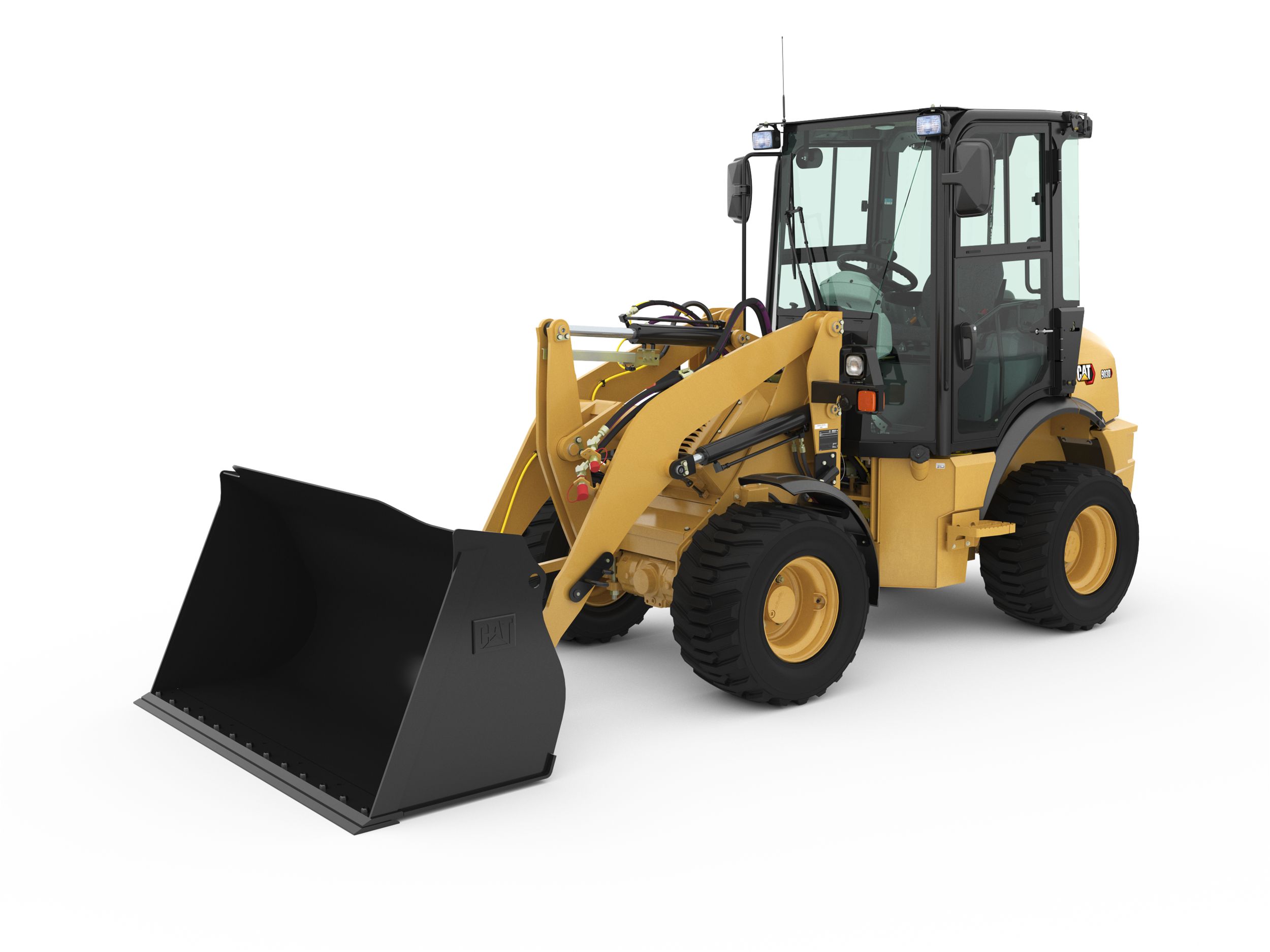
903D Compact Wheel Loader
|
Engine |
| Engine Power - ISO 14396:2002 |
580 hp |
- |
- |
580 hp |
- |
| Engine Model |
Cat® C18 |
Cat C3.6 |
Cat C3.6 |
Cat® C18 |
Cat C2.4* |
| Rated Speed |
1700/rpm |
- |
- |
1,700 rpm |
- |
| Peak Power Speed |
1500/rpm |
- |
- |
1,500 rpm |
- |
| Gross Power - SAE J1995:2014 |
588 hp |
- |
- |
588 hp |
- |
| Net Power - SAE J1349:2011 |
538 hp |
- |
- |
538 hp |
- |
| Bore |
5.7 in |
3.85 in |
3.85 in |
5.7 in |
3.4 in |
| Stroke |
7.2 in |
4.72 in |
4.72 in |
7.2 in |
4 in |
| Displacement |
1105 in³ |
220 in³ |
220 in³ |
1105 in³ |
147 in² |
| Peak Torque - 1,200 rpm |
2104 lbf·ft |
- |
- |
2230 lbf·ft |
- |
| Torque Rise |
58 % |
- |
- |
58% |
- |
| Note (1) |
Three engine emission options are available: 1. Meets U.S. EPA Tier 4 Final, EU Stage V, and Japan 2014 emission standards. 2. Meets Brazil MAR-1 emission standards, equivalent to U.S. EPA Tier 3 and EU Stage IIIA. 3. Meets China Nonroad Stage IV emissio |
- |
- |
Two engine emissions options are available: 1. Meets U.S. EPA Tier 4 Final, EU Stage V, and Japan 2014 emission standards. 2. Meets Brazil MAR-1 emission standards, equivalent to U.S. EPA Tier 3 and EU Stage IIIA. |
- |
| Note (2) |
Net power advertised is the power available at the flywheel when the engine is equipped with fan at minimum speed, air intake system, exhaust system, and alternator. |
- |
- |
Net power advertised is the power available at the flywheel when the engine is equipped with fan at minimum speed, air intake system, exhaust system, and alternator. |
- |
| Maximum Gross Power |
- |
110 hp |
121 hp |
- |
42 hp |
| Rated Net Power - Rated Engine Speed |
- |
2200 r/min |
2200 r/min |
- |
- |
| Maximum Gross Power - Rated Engine Speed |
- |
1800 r/min |
2200 r/min |
- |
- |
| Rated Net Power - SAE J1349 |
- |
99 hp |
120 hp |
- |
- |
| Maximum Gross Power - ISO 14396 (metric) |
- |
112 hp |
122 hp |
- |
- |
| Rated Net Power - ISO 9249 |
- |
98 hp |
118 hp |
- |
- |
| Maximum Gross Torque - SAE J1995 |
- |
335 ft·lbf |
372 ft·lbf |
- |
- |
| Maximum Gross Torque - ISO 14396 |
- |
332 ft·lbf |
369 ft·lbf |
- |
- |
| Maximum Net Torque - SAE J1349 |
- |
329 ft·lbf |
366 ft·lbf |
- |
- |
| Maximum Net Torque - ISO 9249 |
- |
327 ft·lbf |
363 ft·lbf |
- |
- |
| Emissions |
- |
Engine meets Tier 4 Final/Stage V emission standards. |
Engine meets Tier 4 Final/Stage V emission standards. |
- |
- |
| Note |
- |
Net power advertised is the power available at the flywheel plus front drive implement pump when the engine is equipped with fan, air cleaner, muffler and alternator. |
Net power advertised is the power available at the flywheel plus front drive implement pump when the engine is equipped with fan, air cleaner, muffler and alternator. |
- |
*Engine meets U.S. EPA Tier 4 Final emission standards. |
| Maximum Gross Power - ISO 14396 |
- |
110 hp |
121 hp |
- |
- |
| Gross Power |
- |
- |
- |
- |
42 hp |
| Net Power - 2,200 rpm - SAE J1349 R-ing |
- |
- |
- |
- |
40 hp |
| Net Power - 2,200 rpm - ISO 9249 R-ing |
- |
- |
- |
- |
40 hp |
Operating Specifications |
| Operating Weight |
112574 lb |
- |
- |
116362 lb |
- |
| Bucket Capacity Range |
4.7-13 m3 (6.2-17 yd3) |
- |
- |
4.7-13 m3 (6.2-17 yd3) |
- |
| Rated Payload - Quarry Face |
12.5 t |
- |
- |
12.5 t |
- |
| Rated Payload - Loose Material |
16 t |
- |
- |
16 t |
- |
| Cat Truck Match - Standard |
770 - 772 |
- |
- |
- |
- |
| Cat Truck Match - High Lift |
773 - 775 |
- |
- |
- |
- |
Transmission |
| Transmission Type |
Cat planetary powershift |
- |
- |
Cat switched reluctance electric drive |
- |
| Forward - 1 |
4 mile/h |
- |
- |
- |
- |
| Forward - 2 |
7.2 mile/h |
- |
- |
- |
- |
| Forward - 3 |
12.7 mile/h |
- |
- |
- |
- |
| Forward - 4 |
21.6 mile/h |
- |
- |
- |
- |
| Reverse - 1 |
4.7 mile/h |
- |
- |
- |
- |
| Reverse - 2 |
8.3 mile/h |
- |
- |
- |
- |
| Reverse - 3 |
14.4 mile/h |
- |
- |
- |
- |
| Direct Drive - Forward 1 |
Lock-up disabled |
- |
- |
- |
- |
| Direct Drive - Forward 2 |
7.8 mile/h |
- |
- |
- |
- |
| Direct Drive - Forward 3 |
13.9 mile/h |
- |
- |
- |
- |
| Direct Drive - Forward 4 |
24.4 mile/h |
- |
- |
- |
- |
| Direct Drive - Reverse 1 |
5 mile/h |
- |
- |
- |
- |
| Direct Drive - Reverse 2 |
8.9 mile/h |
- |
- |
- |
- |
| Direct Drive - Reverse 3 |
15.8 mile/h |
- |
- |
- |
- |
| Note |
- |
*Creeper Control allows speed control from a stand still up to 10 km/h (6.3 mph). The Creeper Control will only work in Range 1. |
*Creeper Control allows speed control from a stand still up to 10 km/h (6.3 mph). The Creeper Control will only work in Range 1. |
- |
- |
| Forward and Reverse - Speed Range 3 |
- |
25 mile/h |
25 mile/h |
- |
- |
| Forward and Reverse - Speed Range 1* |
- |
6.3 mile/h |
6.3 mile/h |
- |
- |
| Forward and Reverse - Speed Range 2* |
- |
12.5 mile/h |
12.5 mile/h |
- |
- |
| Forward 1 (virtual) |
- |
- |
- |
4.3 mile/h |
- |
| Forward 2 (virtual) |
- |
- |
- |
7 mile/h |
- |
| Forward 3 (virtual) |
- |
- |
- |
13.8 mile/h |
- |
| Forward 4 (virtual) |
- |
- |
- |
20 mile/h |
- |
| Reverse 1 (virtual) |
- |
- |
- |
4.3 mile/h |
- |
| Reverse 2 (virtual) |
- |
- |
- |
7 mile/h |
- |
| Reverse 3 (virtual) |
- |
- |
- |
17.5 mile/h |
- |
| Travel Speed |
- |
- |
- |
- |
12.4 mile/h |
Hydraulic System - Lift/Tilt |
| Lift/Tilt System - Circuit |
EH- Positive Flow Control, Flow Sharing |
- |
- |
EH-Positive Flow Control, Flow Sharing |
- |
| Lift/Tilt System - Pump |
Variable displacement piston |
- |
- |
Variable displacement piston |
- |
| Maximum Flow at 1,400-1,860 rpm |
153 gpm |
- |
- |
- |
- |
| Relief Valve Setting - Lift/Tilt |
4757 psi |
- |
- |
4757 psi |
- |
| Cylinders, Double Acting - Lift, Bore and Stroke |
210 mm × 1050 mm (8.7 in × 41.3 in) |
- |
- |
- |
- |
| Cylinders, Double Acting - Tilt, Bore and Stroke |
266 mm × 685 mm (8.7 in × 27 in) |
- |
- |
- |
- |
| Pilot System |
Variable displacement piston |
- |
- |
- |
- |
| Relief Valve Setting - Main |
551 psi |
- |
- |
- |
- |
| Maximum Flow at 1,400-1,600 rpm |
- |
- |
- |
153 gpm |
- |
| Lift Cylinder - Bore |
- |
- |
- |
8.7 in |
- |
| Lift Cylinder - Stroke |
- |
- |
- |
41.3 in |
- |
| Tilt Cylinder - Bore |
- |
- |
- |
8.7 in |
- |
| Tilt Cylinder - Stroke |
- |
- |
- |
27 in |
- |
Hydraulic Cycle Time (1,400-1,860 rpm) |
| Rack Back |
4.5 s |
- |
- |
- |
- |
| Raise |
8 s |
- |
- |
- |
- |
| Dump |
2.2 s |
- |
- |
- |
- |
| Lower Float Down |
3.5 s |
- |
- |
- |
- |
| Total Hydraulic Cycle Time - Empty Bucket |
18.2 s |
- |
- |
- |
- |
Hydraulic System - Steering |
| Steering System - Circuit |
Pilot, load sensing |
- |
- |
Pilot, load sensing |
- |
| Steering System - Pump |
Piston, variable displacement |
- |
- |
Piston, variable displacement |
- |
| Maximum Flow at 1,400-1,600 rpm |
71.3 gpm |
- |
- |
71.3 gpm |
- |
| Relief Valve Setting - Steering |
4351 psi |
- |
- |
- |
- |
| Total Steering Angle |
86 ° |
- |
- |
86° |
- |
| Steering Cycle Times - High Idle |
3.4 s |
- |
- |
3.4 s |
- |
| Steering Cycle Times - Low Idle |
5.6 s |
- |
- |
5.6 s |
- |
| Steering Cut Off Pressure |
- |
- |
- |
4351 psi |
- |
Air Conditioning System |
| Air Conditioning |
• The air conditioning system on this machine contains the fluorinated greenhouse gas refrigerant R134a or R1234yf. See the label or instruction manual for identification of the gas. • If equipped with R134a (Global Warming Potential = 1430), the system |
- |
- |
The air conditioning system on this machine contains the fluorinated greenhouse gas refrigerant R134a or R1234yf. See the label or instruction manual for identification of the gas. • If equipped with R134a (Global Warming Potential = 1430), the system con |
- |
Axles |
| Front |
Fixed |
Fixed; Locking differential (standard) |
Fixed; Locking differential (standard) |
Fixed |
- |
| Rear |
Trunnion |
Oscillating ±11 degrees; Locking differential (Standard) |
Oscillating ±11 degrees; Locking differential (standard) |
Trunnion |
- |
| Oscillation Angle |
13 ° |
- |
- |
13° |
- |
Brakes |
| Brakes |
ISO 3450:2011 |
- |
- |
ISO 3450:2011 |
- |
Operator's Cab |
| ROPS/FOPS |
ROPS/FOPS meet ISO 3471:2008 and ISO 3449:2005 Level II standards |
- |
- |
ROPS/FOPS meet ISO 3471:2008 and ISO 3449:2005 Level II standards |
- |
Sound Performance - Tier 4 Final / Stage V |
| Operator Sound Pressure Level (ISO 6396:2008) |
73 dB(A) |
- |
- |
72 dB(A) |
- |
| Machine Sound Power Level (ISO 6395:2008) |
111 dB(A) |
- |
- |
109 dB(A) |
- |
| Operator Sound Pressure Level (ISO 6396:2008)* |
72 dB(A) |
- |
- |
72 dB(A) |
- |
| Machine Sound Power Level (ISO 6395:2008)** |
109 dB(A) |
- |
- |
109 dB(A) |
- |
| Note (1) |
* For machines in European Union countries and in countries that adopt the “EU Directives” and “UK Directives.” |
- |
- |
* For machines in European Union countries and in countries that adopt the “EU Directives” and “UK Directives” |
- |
| Note (2) |
** European Union Directive “2000/14/EC” as amended by “2005/88/EC” and UK Noise Regulation 2001 No. 1701. |
- |
- |
** European Union Directive “2000/14/EC” as amended by “2005/88/EC” and UK Noise Regulation 2001 No. 1701 |
- |
| Note (3) |
The machine sound power level was measured according to ISO 6395:2008. The measurement was conducted at 70% of the maximum engine cooling fan speed. |
- |
- |
The machine sound power level was measured according to ISO 6395:2008. The measurement was conducted at 70% of the maximum engine cooling fan speed. |
- |
| Note (4) |
The operator sound pressure level was measured according to ISO 6396:2008. The measurement was conducted at 70% of the maximum engine cooling fan speed. |
- |
- |
The operator sound pressure level was measured according to ISO 6396:2008. The measurement was conducted at 70% of the maximum engine cooling fan speed. |
- |
| Note (5) |
Hearing protection may be needed when the machine is operated with a cab that is not properly maintained or when the doors or windows are open for extended periods or in a noisy environment. |
- |
- |
Hearing protection may be needed when the machine is operated with a cab that is not properly maintained or when the doors or windows are open for extended periods or in a noisy environment. |
- |
Sound Performance - Tier 3 / Stage IIIA |
| Operator Sound Pressure Level (ISO 6396:2008) |
73 dB(A) |
- |
- |
72 dB(A) |
- |
| Machine Sound Power Level (ISO 6395:2008) |
112 dB(A) |
- |
- |
110 dB(A) |
- |
| Operator Sound Pressure Level (ISO 6396:2008)* |
72 dB(A) |
- |
- |
72 dB(A) |
- |
| Machine Sound Power Level (ISO 6395:2008)** |
110 dB(A) |
- |
- |
110 dB(A) |
- |
| Note (1) |
* For machines in European Union countries and in countries that adopt the “EU Directives” and “UK Directives.” |
- |
- |
* For machines in European Union countries and in countries that adopt the “EU Directives” and “UK Directives” |
- |
| Note (2) |
** European Union Directive “2000/14/EC” as amended by “2005/88/EC” and UK Noise Regulation 2001 No. 1701. |
- |
- |
** European Union Directive “2000/14/EC” as amended by “2005/88/EC” and UK Noise Regulation 2001 No. 1701 |
- |
| Note (3) |
The machine sound power level was measured according to ISO 6395:2008. The measurement was conducted at 70% of the maximum engine cooling fan speed. |
- |
- |
The machine sound power level was measured according to ISO 6395:2008. The measurement was conducted at 70% of the maximum engine cooling fan speed. |
- |
| Note (4) |
The operator sound pressure level was measured according to ISO 6396:2008. The measurement was conducted at 70% of the maximum engine cooling fan speed. |
- |
- |
The operator sound pressure level was measured according to ISO 6396:2008. The measurement was conducted at 70% of the maximum engine cooling fan speed. |
- |
| Note (5) |
Hearing protection may be needed when the machine is operated with a cab that is not properly maintained or when the doors or windows are open for extended periods or in a noisy environment. |
- |
- |
Hearing protection may be needed when the machine is operated with a cab that is not properly maintained or when the doors or windows are open for extended periods or in a noisy environment. |
- |
Service Refill Capacities |
| Fuel Tank |
188 gal (US) |
43.6 gal (US) |
43.6 gal (US) |
147 gal (US) |
11.4 gal (US) |
| Cooling System |
31.7 gal (US) |
5.7 gal (US) |
5.7 gal (US) |
- |
3 gal (US) |
| Coolant (Validated by Test Cell Fill Quantities) |
33 gal (US) |
- |
- |
- |
- |
| Crankcase |
15.9 gal (US) |
- |
- |
- |
- |
| Diesel Exhaust Fluid Tank (For Tier 4 Final/Stage V Only) |
8.7 gal (US) |
- |
- |
- |
- |
| Transmission |
24.3 gal (US) |
0.8 gal (US) |
0.8 gal (US) |
16 gal (US) |
- |
| Transmission - Validated by Test Cell Fill Quantities |
29 gal (US) |
- |
- |
- |
- |
| Differential - Final Drives - Front |
49.1 gal (US) |
- |
- |
49 gal (US) |
- |
| Differential - Final Drives - Rear |
49.1 gal (US) |
- |
- |
49 gal (US) |
- |
| Hydraulic System Factory Fill |
125.5 gal (US) |
- |
- |
- |
- |
| Hydraulic System - Tank Only |
63.4 gal (US) |
- |
- |
- |
- |
| Note |
• All non-road Tier 4 Final/Stage V diesel engines are required to use ULSD (ultra-low sulfur diesel fuel with 15 ppm of sulfur or less) or ULSD blended with the following lower-carbon intensity fuels** up to: – 20% biodiesel FAME (fatty acid methyl ester |
DEF used in Cat SCR systems must meet the requirements outlined in the International Organization for Standardization (ISO) standard 22241-1. |
DEF used in Cat Selective Catalyst Reduction (SCR) systems must meet the requirements outlined in the International Organization for Standardization (ISO) standard 22241-1. |
Cat U.S. EPA Tier 4 Final, EU Stage V, and Japan 2014 diesel engines are required to use ULSD (ultra-low sulfur diesel fuel with 15 ppm of sulfur or less) and are compatible* with ULSD blended with the following lower-carbon intensity fuels** up to: • 20% |
- |
| Axles - Rear Center Differential |
- |
2 gal (US) |
- |
- |
- |
| Hydraulic System - Including Tank |
- |
25.9 gal (US) |
25.9 gal (US) |
- |
- |
| Diesel Exhaust Fluid (DEF) Tank |
- |
4.8 gal (US) |
4.8 gal (US) |
- |
- |
| Engine Crankcase |
- |
2.6 gal (US) |
2.6 gal (US) |
16 gal (US) |
- |
| Hydraulic Tank |
- |
14.5 gal (US) |
14.5 gal (US) |
- |
- |
| Axles - Front Center Differential |
- |
2 gal (US) |
- |
- |
- |
| Axles - Rear |
- |
- |
4.5 gal (US) |
- |
- |
| Axles - Front |
- |
- |
4.5 gal (US) |
- |
- |
| Cooling System - Jacket Water |
- |
- |
- |
30 gal (US) |
- |
| Cooling Systems - Power Train |
- |
- |
- |
8 gal (US) |
- |
| Diesel Exhaust Fluid Tank |
- |
- |
- |
8.7 gal (US) |
- |
| Hydraulic System - Implement/Steering |
- |
- |
- |
126 gal (US) |
- |
| Hydraulic System |
- |
- |
- |
- |
6.3 gal (US) |
| Engine Oil |
- |
- |
- |
- |
2.4 gal (US) |
Dimensions (Approximate) - Standard Lift Linkage |
| Ground to Top of ROPS |
13.8 ft |
- |
- |
- |
- |
| Ground to Top of Exhaust Stacks |
14.8 ft |
- |
- |
- |
- |
| Ground to Top of Hood |
10.9 ft |
- |
- |
- |
- |
| Rear Axle - Centerline to Bumper |
10.5 ft |
- |
- |
- |
- |
| Front Axle Centerline to Bucket Tip |
14 ft |
- |
- |
- |
- |
| Wheel Base |
14.9 ft |
- |
- |
- |
- |
| Maximum Overall Length |
39.3 ft |
- |
- |
- |
- |
| Ground to Lower Hitch Clearance |
1.9 ft |
- |
- |
- |
- |
| Clearance at Maximum Lift |
11.9 ft |
- |
- |
- |
- |
| B-Pin Height - Maximum Lift |
18 ft |
- |
- |
- |
- |
| Maximum Overall Height - Bucket Raised |
24.5 ft |
- |
- |
- |
- |
| Reach - Maximum Lift |
6.5 ft |
- |
- |
- |
- |
Dimensions (Approximate) - High Lift Linkage |
| Ground to Top of ROPS |
13.8 ft |
- |
- |
- |
- |
| Ground to Top of Exhaust Stacks |
14.8 ft |
- |
- |
- |
- |
| Ground to Top of Hood |
10.9 ft |
- |
- |
- |
- |
| Rear Axle - Centerline to Bumper |
10.5 ft |
- |
- |
- |
- |
| Front Axle Centerline to Bucket Tip |
15.3 ft |
- |
- |
- |
- |
| Wheel Base |
14.9 ft |
- |
- |
- |
- |
| Maximum Overall Length |
40.7 ft |
- |
- |
- |
- |
| Ground to Lower Hitch Clearance |
1.9 ft |
- |
- |
- |
- |
| Clearance at Maximum Lift |
13.3 ft |
- |
- |
- |
- |
| B-Pin Height - Maximum Lift |
19.3 ft |
- |
- |
- |
- |
| Maximum Overall Height - Bucket Raised |
25.8 ft |
- |
- |
- |
- |
| Reach - Maximum Lift |
6.8 ft |
- |
- |
- |
- |
Weights |
| Operating Weight |
- |
19103 lb |
21742 lb |
- |
9414 lb |
Buckets |
| Bucket Capacities |
- |
1.3-3.5 m3 (1.7-4.6 yd3) |
1.3-3.5 m3 (1.7-4.6 yd3) |
- |
0.6-1.0 m3 (0.8-1.3 yd3) |
| Bucket Capacities - General Purpose |
- |
1.3-1.9 m³ (1.7-2.5 yd³) |
1.3-1.9 m³ (1.7-2.5 yd³) |
- |
0.6 m3 (0.8 yd3) |
| Bucket Capacities - Light Material |
- |
2.5-3.5 m³ (3.3-4.6 yd³) |
2.5-3.5 m³ (3.3-4.6 yd³) |
- |
1.0 m3 (1.3 yd3) |
Sustainability |
| Recyclability |
- |
95% |
95% |
- |
97% |
Cab |
| ROPS |
- |
ISO 3471:2008 |
ISO 3471:2008 |
- |
ISO 3471:2008 |
| FOPS |
- |
ISO 3449:2005 |
ISO 3449:2005 |
- |
ISO 3449:2005 Level I |
| Note (4) |
- |
*The measurements were conducted with the cab doors and windows closed. |
*The measurements were conducted with the cab doors and windows closed. |
- |
- |
| Note (2) |
- |
The declared dynamic operator sound pressure levels per ISO 6396:2008*, when the cab is properly installed and maintained, is 77 dB(A). |
The declared dynamic operator sound pressure levels per ISO 6396:2008*, when the cab is properly installed and maintained, is 77 dB(A). |
- |
- |
| Note (3) |
- |
The labelled sound power level for the CE marked configurations when measured according to the test procedure and conditions specified in 2000/14/EC (as amended by 2005/88/EC) is 103 dB(A). |
The labelled sound power level for the CE marked configurations when measured according to the test procedure and conditions specified in 2000/14/EC (as amended by 2005/88/EC) is 103 dB(A). |
- |
- |
| Note (1) |
- |
Cab and Rollover Protective Structures (ROPS) are standard in North America and Europe. |
Cab and Rollover Protective Structures (ROPS) are standard in North America and Europe. |
- |
- |
Steering |
| Maximum Flow - Steering Pump |
- |
22 gpm |
21.7 gpm |
- |
- |
| Number of Steering Wheel Turns - Full Left to Full Right or Full Right to Full Left |
- |
3.75 turns |
3.4 turns |
- |
- |
| Steering Cycle Times - Full Left to Full Right - At 2,350 rpm: 90 rpm Steering Wheel Speed |
- |
2.8 s |
2.3 s |
- |
- |
| Maximum Working Pressure - Steering Pump |
- |
3263 psi |
3190 psi |
- |
- |
| Steering Articulation Angle - Each Direction |
- |
40 ° |
40 ° |
- |
- |
Loader Hydraulic System |
| Relief Pressure - Tilt Cylinder - 3rd Function Maximum Working Pressure |
- |
3046 psi |
- |
- |
- |
| Maximum Flow - Implement Pump |
- |
39 gpm |
43.6 gpm |
- |
- |
| Maximum Flow - Implement Pump - 3rd Function, Maximum Flow, Standard |
- |
24 gpm |
25 gpm |
- |
- |
| Relief Pressure - Tilt Cylinder - 4th Function Maximum Working Pressure |
- |
3046 psi |
- |
- |
- |
| Hydraulic Cycle Time - Total Cycle Time |
- |
12.5 s |
11.5 s |
- |
- |
| Hydraulic Cycle Time - Raise, Ground Level to Maximum Lift |
- |
5.2 s |
4.8 s |
- |
- |
| Maximum Flow - Implement Pump - 4th Function, Maximum Flow |
- |
24 gpm |
- |
- |
- |
| Hydraulic Cycle Time - Dump, at Maximum Reach |
- |
1.4 s |
1.8 s |
- |
- |
| Relief Pressure - Tilt Cylinder |
- |
4931 psi |
4641 psi |
- |
- |
| Maximum Flow - Implement Pump - 3rd Function, Maximum Flow, High |
- |
32 gpm |
40 gpm |
- |
- |
| Maximum Working Pressure - Implement Pump |
- |
4061 psi |
4061 psi |
- |
- |
| Hydraulic Cycle Time - Rackback |
- |
2.2 s |
2.2 s |
- |
- |
| Hydraulic Cycle Time - Float Down, Maximum Lift to Ground Level |
- |
3.7 s |
2.7 s |
- |
- |
| Relief Pressure - Tilt Cylinder - 4th Function Relief Pressure |
- |
- |
4641 psi |
- |
- |
| Note |
- |
- |
All cycle times listed are with cylinder snubbing turned off. |
- |
- |
| Maximum Flow - Implement Pump - 4rd Function, Maximum Flow |
- |
- |
25 gpm |
- |
- |
| Hydraulic Cycle Time - Lift |
- |
- |
- |
- |
4.4 s |
| Hydraulic Cycle Time - Dump |
- |
- |
- |
- |
0.7 s |
Tires |
| Other Choices Include |
- |
17.5 R25 L3 XHA2; 17.5-25 L2/L3 SGL; 17.5-25 L3 HRL D/L-3A; 17.5 R25 L2 Snow; 17.5 R25 Solid |
17.5 R25 L3 XHA2; 20.5 R25 L3 XHA3; 17.5-25 L2/L3 SGL; 20.5-25 L2/L3 SGL; 17.5-25 L3 HRL D/L-3A; 17.5 R25 L2 Snow; 20.5 R25 L2 Snow; 17.5 R25 Solid |
- |
- |
| Note (1) |
- |
Other tire choices are available. Contact your Cat dealer for details. |
Other tire choices are available. Contact your Cat dealer for details. |
- |
- |
| Standard Size |
- |
17.5 R25 L2 XTLA |
17.5 R25 L2 XTLA |
- |
- |
| Note (3) |
- |
Caterpillar recommends that you consult a tire supplier to evaluate all conditions before selecting a tire model. |
Caterpillar recommends that you consult a tire supplier to evaluate all conditions before selecting a tire model. |
- |
- |
| Note (2) |
- |
In certain applications, the loader’s productive capabilities may exceed the tire’s tonnes-km/h (ton-mph) capabilities. |
In certain applications, the loader’s productive capabilities may exceed the tire’s tonnes-km/h (ton-mph) capabilities. |
- |
- |
Hydraulic Cycle Times |
| Rack Back |
- |
- |
- |
4.5 s |
- |
| Raise |
- |
- |
- |
8 s |
- |
| Dump |
- |
- |
- |
2.2 s |
- |
| Lower Float Down |
- |
- |
- |
3.5 s |
- |
| Total Hydraulic Cycle Time |
- |
- |
- |
18.2 s |
- |
Dimensions (Approximate) - Standard Lift |
| Ground to Top of ROPS |
- |
- |
- |
13.8 ft |
- |
| Ground to Top of Exhaust Stacks |
- |
- |
- |
14.8 ft |
- |
| Ground to Top of Hood |
- |
- |
- |
10.9 ft |
- |
| Ground to Bumper Clearance |
- |
- |
- |
3.1 ft |
- |
| Rear Axle - Centerline to Bumper |
- |
- |
- |
10.5 ft |
- |
| Front Axle Centerline to Bucket Tip |
- |
- |
- |
14 ft |
- |
| Wheel Base |
- |
- |
- |
14.9 ft |
6.42 ft |
| Maximum Overall Length |
- |
- |
- |
39.3 ft |
- |
| Ground to Lower Hitch Clearance |
- |
- |
- |
1.9 ft |
- |
| Ground to Center of Axles |
- |
- |
- |
3.2 ft |
- |
| Clearance at Maximum Lift |
- |
- |
- |
11.9 ft |
- |
| B-Pin Height - Maximum Lift |
- |
- |
- |
18 ft |
- |
| Maximum Overall Height - Bucket Raised |
- |
- |
- |
24.5 ft |
- |
| Reach - Maximum Lift |
- |
- |
- |
6.5 ft |
- |
| Note |
- |
- |
- |
Specifications are calculated with 6.9 m3 (9.0 yd3) rock bucket and Michelin XLDD2 with 978 mm (3.2 ft) centerline of rear axle height. |
- |
| Cab Height |
- |
- |
- |
- |
8.25 ft |
| Ground Clearance |
- |
- |
- |
- |
10 in |
| Overall Length - With Bucket* |
- |
- |
- |
- |
15.75 ft |
| Reach at Maximum Dump Height* |
- |
- |
- |
- |
2.33 ft |
| Dig Depth |
- |
- |
- |
- |
6 in |
| Maximum Dump Height* |
- |
- |
- |
- |
7.5 ft |
| Load Over Height |
- |
- |
- |
- |
9.17 ft |
| Hinge Pin at Maximum Height |
- |
- |
- |
- |
10.08 ft |
| Departure Angle - Degrees |
- |
- |
- |
- |
30° |
| Overall Length - With Forks |
- |
- |
- |
- |
17.08 ft |
| Reach - Ground Level |
- |
- |
- |
- |
2.67 ft |
| Maximum Reach |
- |
- |
- |
- |
4.5 ft |
| Fork Depth Above Ground |
- |
- |
- |
- |
2 in |
| Fork Height at Maximum Reach |
- |
- |
- |
- |
4.67 ft |
| Maximum Fork Height |
- |
- |
- |
- |
9.83 ft |
| Fork Reach at Maximum Height |
- |
- |
- |
- |
2 ft |
| Turning Radius - Over Bucket* |
- |
- |
- |
- |
13.17 ft |
| Turning Radius - Inside Tire** |
- |
- |
- |
- |
5.92 ft |
| Width - Over Bucket* |
- |
- |
- |
- |
5.83 ft |
| Tire Gauge |
- |
- |
- |
- |
4.33 ft |
| Machine Width** |
- |
- |
- |
- |
5.58 ft |
| Articulation Angle |
- |
- |
- |
- |
40° |
| Steering Angle |
- |
- |
- |
- |
80° |
| Dump Angle at Maximum Height |
- |
- |
- |
- |
40° |
| Note (1) |
- |
- |
- |
- |
*Vary with bucket size. |
| Note (2) |
- |
- |
- |
- |
**Vary with tire size. |
| Note (3) |
- |
- |
- |
- |
Dimensions listed are based on the machine configured with cab with air conditioning, remote quick coupler, general purpose bucket or 1067 mm (42 in) forks, 75 kg (165 lb) operator, 33 × 15.5-16.5, 12 PR tires, without ride control, without precleaner. |
Dimensions (Approximate) - High Lift |
| Ground to Top of ROPS |
- |
- |
- |
13.8 ft |
- |
| Ground to Top of Exhaust Stacks |
- |
- |
- |
14.8 ft |
- |
| Ground to Top of Hood |
- |
- |
- |
10.9 ft |
- |
| Ground to Bumper Clearance |
- |
- |
- |
3.1 ft |
- |
| Rear Axle - Centerline to Bumper |
- |
- |
- |
10.5 ft |
- |
| Front Axle Centerline to Bucket Tip |
- |
- |
- |
15.3 ft |
- |
| Wheel Base |
- |
- |
- |
14.9 ft |
6.42 ft |
| Maximum Overall Length |
- |
- |
- |
40.7 ft |
- |
| Ground to Lower Hitch Clearance |
- |
- |
- |
1.9 ft |
- |
| Ground to Center of Axles |
- |
- |
- |
3.2 ft |
- |
| Clearance at Maximum Lift |
- |
- |
- |
13.3 ft |
- |
| B-Pin Height - Maximum Lift |
- |
- |
- |
19.3 ft |
- |
| Maximum Overall Height - Bucket Raised |
- |
- |
- |
25.8 ft |
- |
| Reach - Maximum Lift |
- |
- |
- |
6.8 ft |
- |
| Note |
- |
- |
- |
Specifications are calculated with 6.9 m3 (9.0 yd3) rock bucket and Michelin XLDD2 with 978 mm (3.2 ft) centerline of rear axle height. |
- |
| Cab Height |
- |
- |
- |
- |
8.25 ft |
| Ground Clearance |
- |
- |
- |
- |
10 in |
| Overall Length - With Bucket* |
- |
- |
- |
- |
16.17 ft |
| Reach at Maximum Dump Height* |
- |
- |
- |
- |
2.42 ft |
| Dig Depth |
- |
- |
- |
- |
8 in |
| Maximum Dump Height* |
- |
- |
- |
- |
8 ft |
| Load Over Height |
- |
- |
- |
- |
9.67 ft |
| Hinge Pin at Maximum Height |
- |
- |
- |
- |
10.58 ft |
| Departure Angle - Degrees |
- |
- |
- |
- |
30° |
| Overall Length - With Forks |
- |
- |
- |
- |
17.58 ft |
| Reach - Ground Level |
- |
- |
- |
- |
3.25 ft |
| Maximum Reach |
- |
- |
- |
- |
4.92 ft |
| Fork Depth Above Ground |
- |
- |
- |
- |
2 in |
| Fork Height at Maximum Reach |
- |
- |
- |
- |
4.67 ft |
| Maximum Fork Height |
- |
- |
- |
- |
10.33 ft |
| Fork Reach at Maximum Height |
- |
- |
- |
- |
2 ft |
| Turning Radius - Over Bucket* |
- |
- |
- |
- |
13.42 ft |
| Turning Radius - Inside Tire** |
- |
- |
- |
- |
5.92 ft |
| Width - Over Bucket* |
- |
- |
- |
- |
5.83 ft |
| Tire Gauge |
- |
- |
- |
- |
4.33 ft |
| Machine Width** |
- |
- |
- |
- |
5.58 ft |
| Articulation Angle |
- |
- |
- |
- |
40° |
| Steering Angle |
- |
- |
- |
- |
80° |
| Dump Angle at Maximum Height |
- |
- |
- |
- |
40° |
| Note (1) |
- |
- |
- |
- |
*Vary with bucket size. |
| Note (2) |
- |
- |
- |
- |
**Vary with tire size. |
| Note (3) |
- |
- |
- |
- |
Dimensions listed are based on the machine configured with cab with air conditioning, remote quick coupler, general purpose bucket or 1067 mm (42 in) forks, 75 kg (165 lb) operator, 33 × 15.5-16.5, 12 PR tires, without ride control, without precleaner. |
Dimensions - Millyard Linkage |
| Ground to Top of ROPS |
- |
- |
- |
13.8 ft |
- |
| Ground to Top of Exhaust Stacks |
- |
- |
- |
13.8 ft |
- |
| Ground to Top of Hood |
- |
- |
- |
10.9 ft |
- |
| Ground to Bumper Clearance |
- |
- |
- |
3.1 ft |
- |
| Rear Axle - Centerline to Bumper |
- |
- |
- |
10.5 ft |
- |
| Front Axle Centerline to Fork Tip |
- |
- |
- |
16.5 ft |
- |
| Wheel Base |
- |
- |
- |
14.9 ft |
- |
| Maximum Overall Length |
- |
- |
- |
41.9 ft |
- |
| Ground to Lower Hitch Clearance |
- |
- |
- |
1.9 ft |
- |
| Ground to Center of Front Axle |
- |
- |
- |
3.2 ft |
- |
| Fork Height with Level Arms |
- |
- |
- |
8.1 ft |
- |
| Fork Top Clamp Opening |
- |
- |
- |
13.1 ft |
- |
| Fork Height at Maximum Lift |
- |
- |
- |
17.2 ft |
- |
| Hinge Pin Height at Maximum Lift |
- |
- |
- |
16.1 ft |
- |
| Dump Angle at Maximum Lift |
- |
- |
- |
-39.4 ° |
- |
Hydraulic System |
| Main Relief |
- |
- |
- |
- |
3481 psi |
| 3rd Auxiliary Flow |
- |
- |
- |
- |
14 gpm |
| Hydraulic Cycle Time - Lower, Float |
- |
- |
- |
- |
2.4 s |
Operating Specifications - Standard Lift |
| Tire Size |
- |
- |
- |
- |
33 × 15.5-16.5, 12 PR |
| Rated Bucket Capacity |
- |
- |
- |
- |
0.8 yd³ |
| Breakout Force |
- |
- |
- |
- |
6160 lbf |
| Operating Weight |
- |
- |
- |
- |
9414 lb |
| Rated Operating Load at Full Turn - Bucket*** |
- |
- |
- |
- |
2701 lb |
| Straight Tipping Load - Bucket*** |
- |
- |
- |
- |
6415 lb |
| Full Turn Static Tipping Load - Bucket (ISO 14397-1*)*** |
- |
- |
- |
- |
5401 lb |
| Full Turn Static Tipping Load - Bucket (Rigid Tire**)*** |
- |
- |
- |
- |
5512 lb |
| Rack Back - Transport Position |
- |
- |
- |
- |
51° |
| Rated Operating Load at Full Turn - Forks (EN 474-3:2006, Firm and Level Ground, 500 mm [20 in] Load Center) (80% FTSTL)*** |
- |
- |
- |
- |
3366 lb |
| Rated Operating Load at Full Turn - Forks (EN 474-3:2006, Rough Terrain, 500 mm [20 in] Load Center) (60% FTSTL)*** |
- |
- |
- |
- |
2524 lb |
| Note (1) |
- |
- |
- |
- |
*Full compliance to ISO 14397-1 (2007) Sections 1 thru 6, which requires 2% verification be-tween calculation and testing. |
| Note (2) |
- |
- |
- |
- |
**Compliance to ISO 14397-1 (2007) Sections 1 thru 5. |
| Note (3) |
- |
- |
- |
- |
***Manual quick coupler, precleaner hood. |
| Note (4) |
- |
- |
- |
- |
Operating specifications shown are based on machine equipped with enclosed ROPS cab with air conditioning, remote quick coupler, 75 kg (165 lb) operator and general purpose bucket (GP), without ride control, without precleaner unless otherwise noted. |
Operating Specifications - High Lift |
| Tire Size |
- |
- |
- |
- |
33 × 15.5-16.5, 12 PR |
| Rated Bucket Capacity |
- |
- |
- |
- |
0.8 yd³ |
| Breakout Force |
- |
- |
- |
- |
6204 lbf |
| Operating Weight |
- |
- |
- |
- |
9462 lb |
| Rated Operating Load at Full Turn - Bucket*** |
- |
- |
- |
- |
2502 lb |
| Straight Tipping Load - Bucket*** |
- |
- |
- |
- |
5975 lb |
| Full Turn Static Tipping Load - Bucket (ISO 14397-1*)*** |
- |
- |
- |
- |
5004 lb |
| Full Turn Static Tipping Load - Bucket (Rigid Tire**)*** |
- |
- |
- |
- |
5115 lb |
| Rack Back - Transport Position |
- |
- |
- |
- |
51° |
| Rated Operating Load at Full Turn - Forks (EN 474-3:2006, Firm and Level Ground, 500 mm [20 in] Load Center) (80% FTSTL)*** |
- |
- |
- |
- |
3148 lb |
| Rated Operating Load at Full Turn - Forks (EN 474-3:2006, Rough Terrain, 500 mm [20 in] Load Center) (60% FTSTL)*** |
- |
- |
- |
- |
2361 lb |
| Note (1) |
- |
- |
- |
- |
*Full compliance to ISO 14397-1 (2007) Sections 1 thru 6, which requires 2% verification be-tween calculation and testing. |
| Note (2) |
- |
- |
- |
- |
**Compliance to ISO 14397-1 (2007) Sections 1 thru 5. |
| Note (3) |
- |
- |
- |
- |
***Manual quick coupler, precleaner hood. |
| Note (4) |
- |
- |
- |
- |
Operating specifications shown are based on machine equipped with enclosed ROPS cab with air conditioning, remote quick coupler, 75 kg (165 lb) operator and general purpose bucket (GP), without ride control, without precleaner unless otherwise noted. |
Maximum Material Densities - General Purpose |
| Bucket Type |
- |
- |
- |
- |
General Purpose |
| Rated Capacity |
- |
- |
- |
- |
0.8 yd³ |
| Dump Height |
- |
- |
- |
- |
90 in |
| Maximum Material Density |
- |
- |
- |
- |
3169 lb/yd³ |
| Bucket Width |
- |
- |
- |
- |
70 in |
| Note |
- |
- |
- |
- |
Based on ISO 7546:1983 and rated operating loads at full turn and standard linkage. |
Maximum Material Densities - Light Material |
| Bucket Type |
- |
- |
- |
- |
Light Material |
| Rated Capacity |
- |
- |
- |
- |
1.3 yd³ |
| Dump Height |
- |
- |
- |
- |
85 in |
| Maximum Material Density |
- |
- |
- |
- |
1989 lb/yd³ |
| Bucket Width |
- |
- |
- |
- |
74 in |
| Note |
- |
- |
- |
- |
Based on ISO 7546:1983 and rated operating loads at full turn and standard linkage. |